
PRODUCTS
PRODUCTS
HOT RECOMMENDATION
NEWS

CONTACT US
TEL
+86 0532 85778977
+86 189 5456 7296
sd@luyumachinery.com
Exp. Office Add
Excellence Century Center, Shibei District, Qingdao, China
Factory. Add
Shahe industrial park, Laizhou City, Shandong Province, China
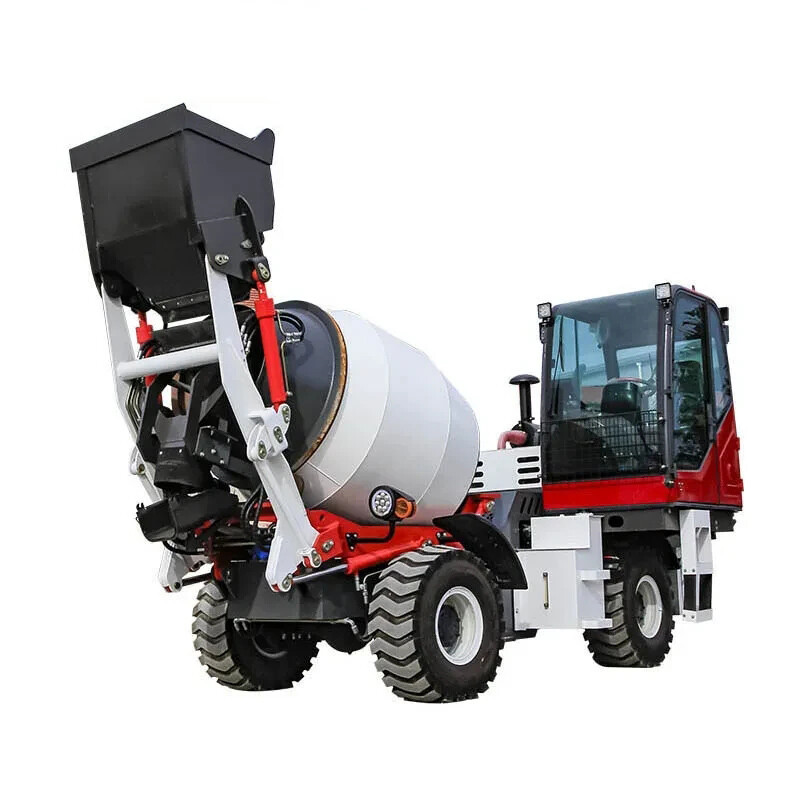
LY5500
LY5500 0.65m³ self loading concrete mixer truck is suitable for civilian construction building, road construction, precast concrete elements production.
‹
›
LY5500 0.65m³ self loading concrete mixer truck is suitable for civilian construction building, road construction, precast concrete elements production.
PARAMETERS
DETAILS

ADVANTAGES
LUYU self loading mixer truck is composed of two major assemblies: chassis and Upper Part. The Upper Part is composed of a mixing tank, a subframe, an inlet and outlet device, an operating system, a hydraulic system, an electrical system, a water supply system, and a guardrail. The specific structure is shown in the figure below:
FAQ
Prev:OXT1304
Next:LY4000
Inquiry
Our manager will contact you within 30 minutes of working hours.

Send Your Inquiry